*bump* So, I received my
LCDs from China, and I set to work doing some testing. Notably, the description says that it supports 8-bit and 16-bit transfer modes, and the ILI9326 certainly supports 8-bit, 9-bit, 16-bit, and 18-bit i80 transfers, but there didn't seem to be an exposed pin to switch between 8-bit and 16-bit mode. I'm making the educated guess that pin 1 on the LCD, marked "NC" in the one blurry diagram the Aliexpress seller page provides, is actually the ID0 pin
for the ILI9326, especially given its order among the pins and the fact that it does indeed appear to be connected.
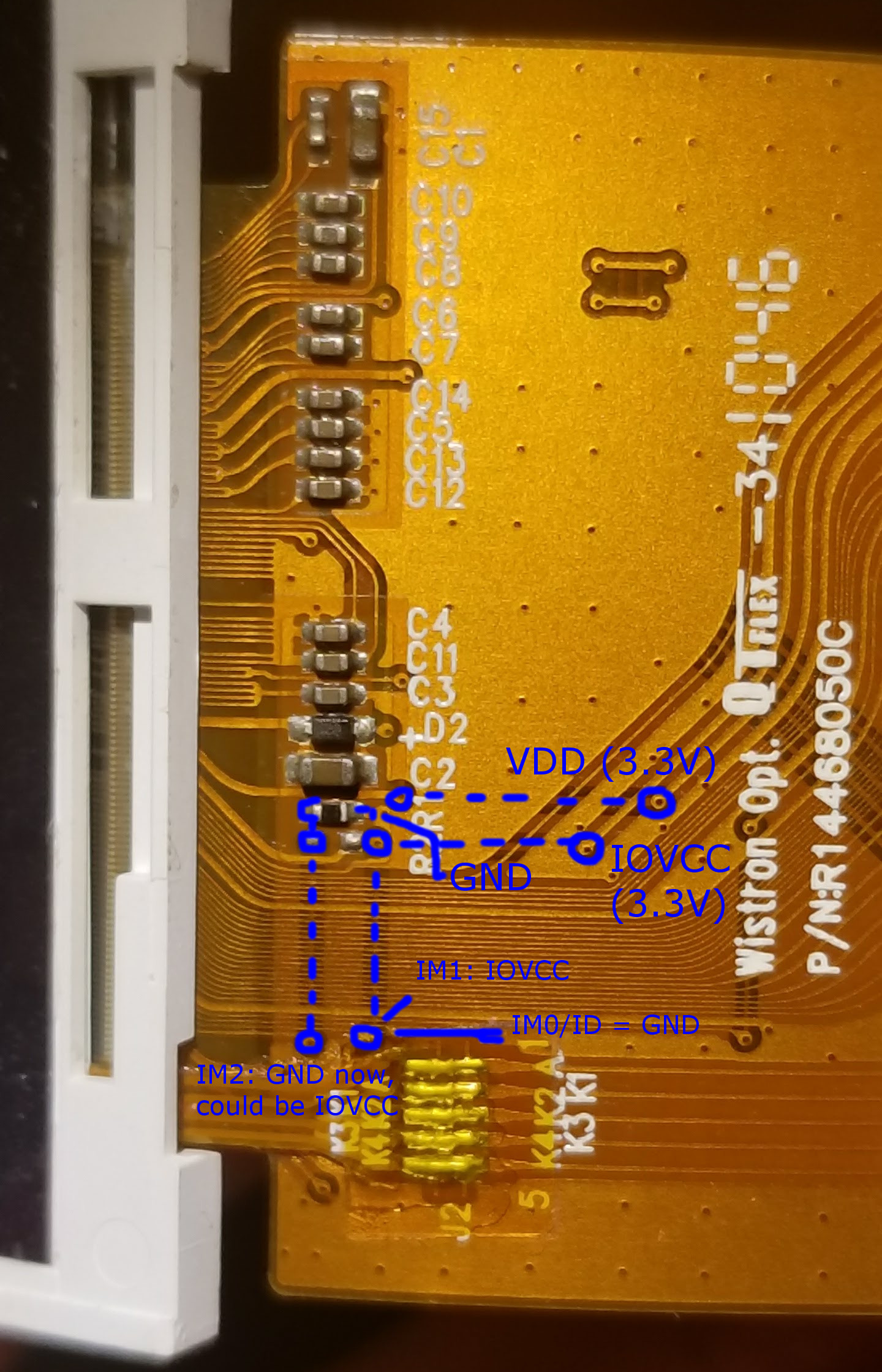
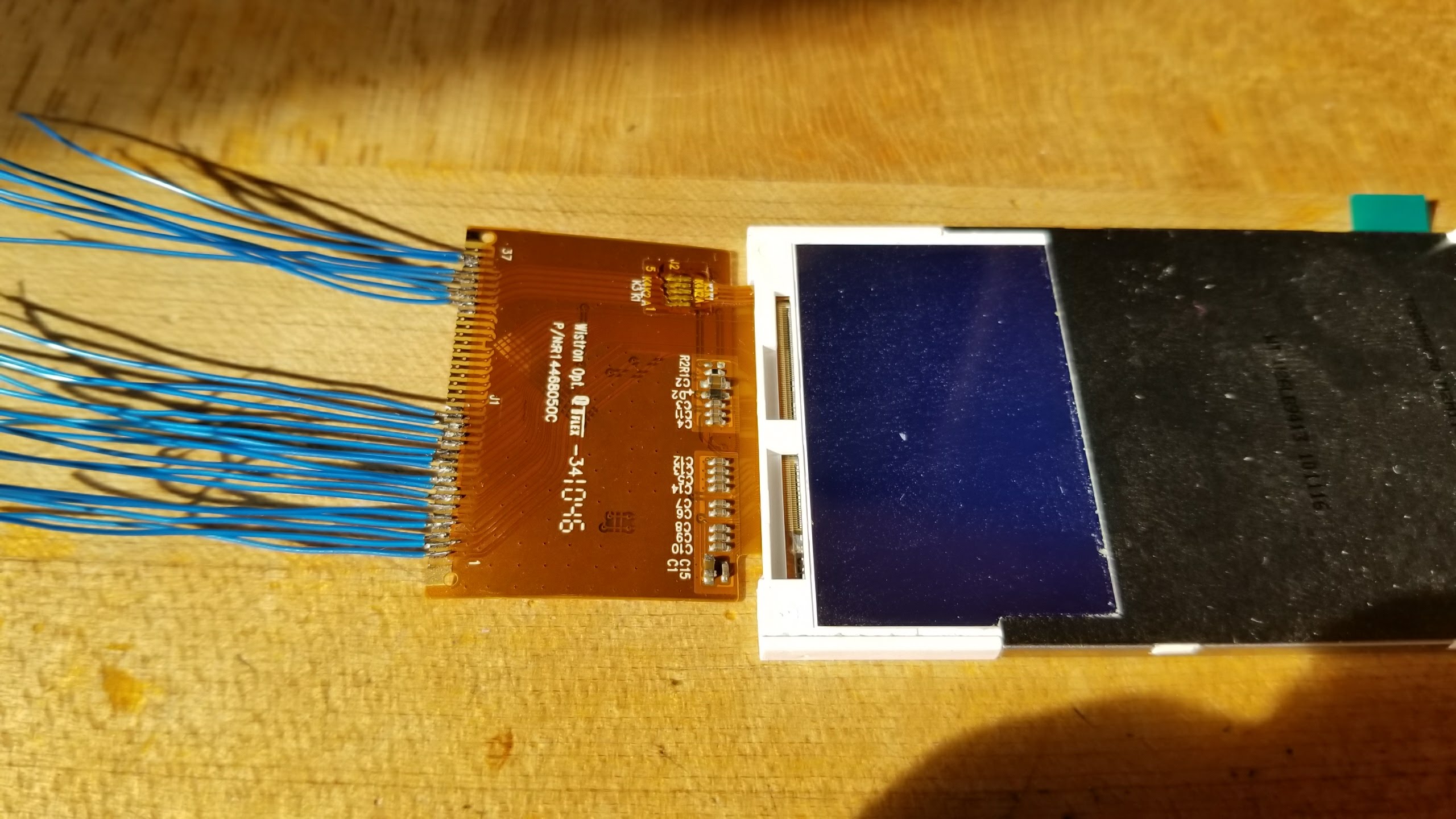
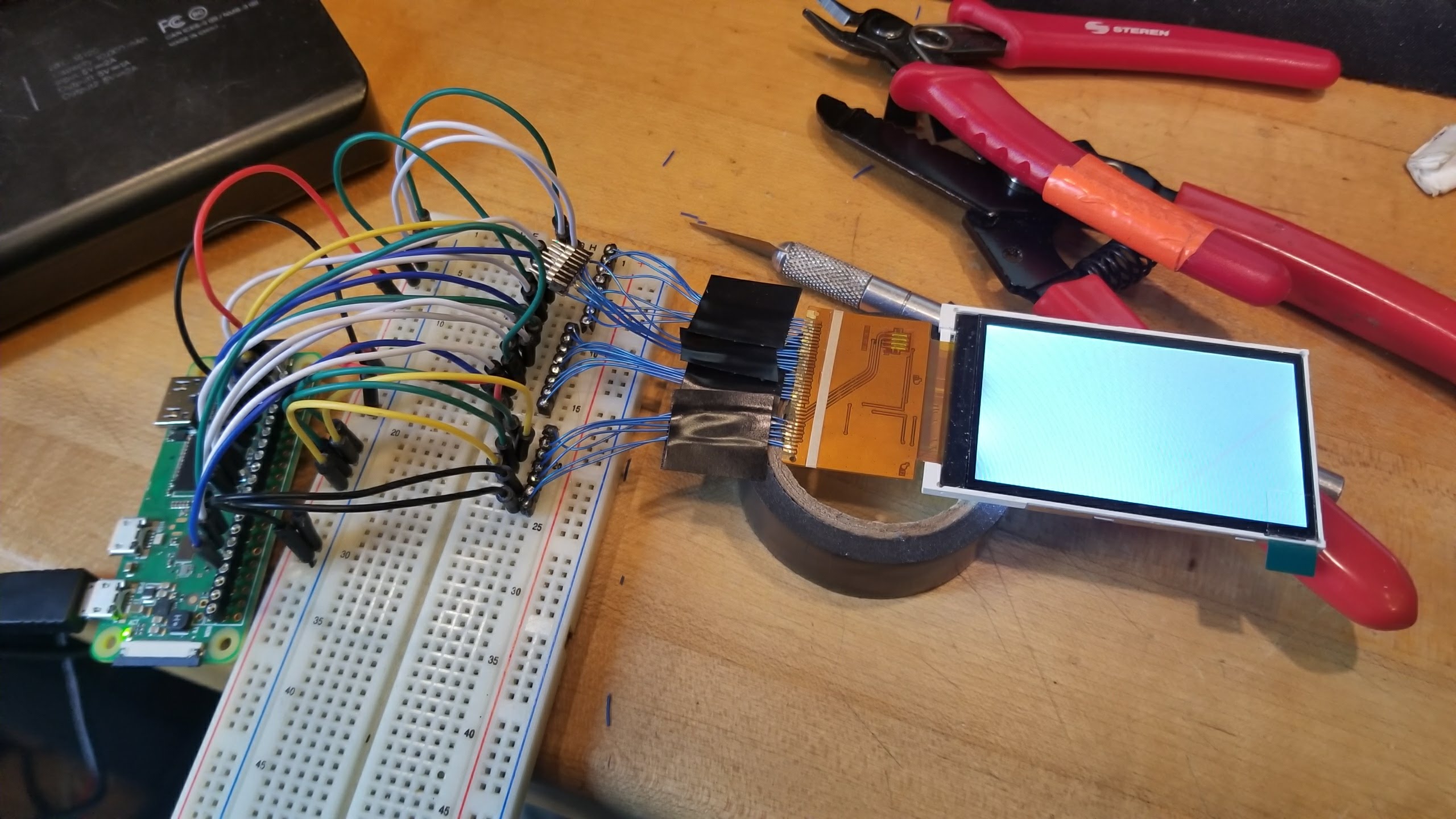
My first order of business was trying to solder some leads to the LCD to control it. I connected to "NC" (let's just call it ID0 for now), IOVCC, VCC, GND, RD, WR, CS, RS (or DC if you prefer), DB0-DB7, and LEDA and LEDK1-4. I used 30AWG wire, gently tacked onto the 0.8mm-spaced (0.5mm x 2.0mm) pads.
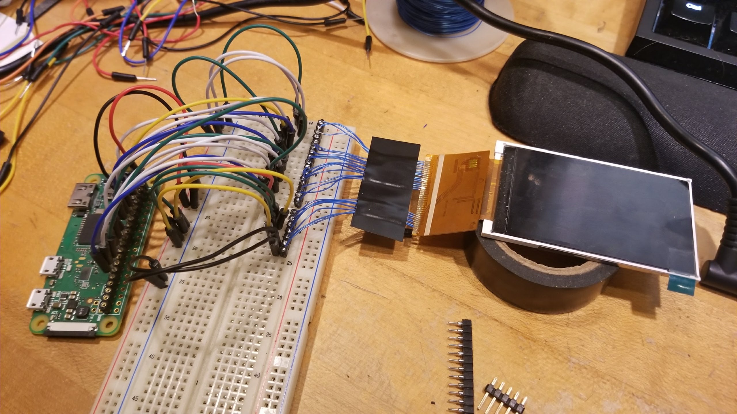
My first test with the Raspberry Pi Zero W and
fbtft yielded only an all-white, uninitialized screen. For future reference, my command (encoding information including my GPIO mapping) is currently thus:
Code: sudo modprobe fbtft_device custom name=fb_ili9325 buswidth=8 gpios=cs:2,dc:3,wr:4,reset:17,db00:27,db01:22,db02:10,db03:9,db04:11,db05:5,db06:6,db07:13 width=240 height=400
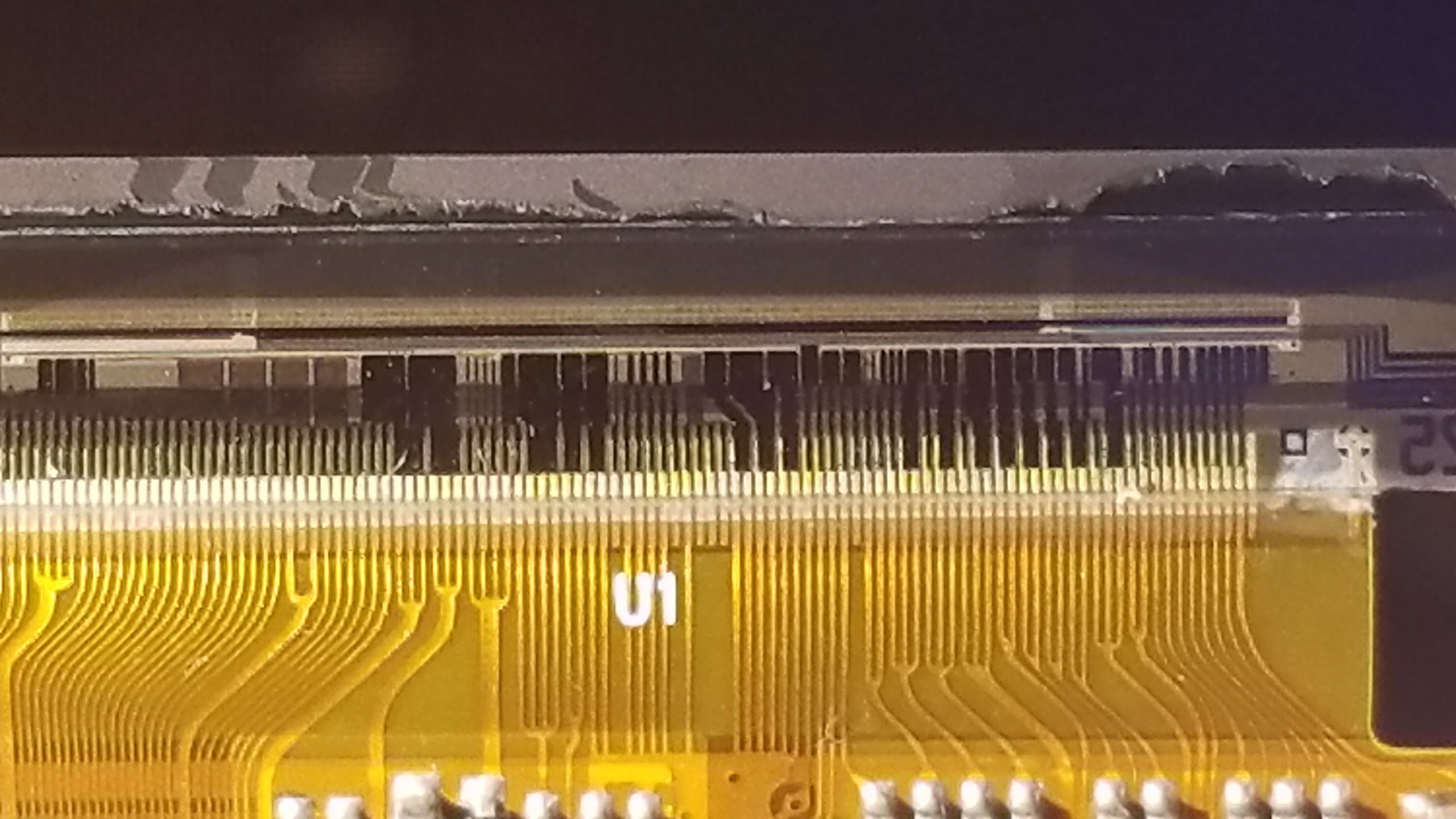
Further troubleshooting showed that my connections all seemed correct, non-crossing, and low-resistance. I noticed, however, that i80 8-bit mode for the ILI9326 requires using bits 9-16 (which I believe are my LCD module's DB8-DB15). I therefore gently separated out the header I had already attached to DB0-DB7, and added a header for DB8-DB15. Unfortunately, I still have no joy. I noticed that it looks like some of the fine copper connections have hairline fractures in them, presumably from the mechanical stress of the wires attached, so I may (1) try to solder across the gaps, or (2) just grab one of these and use it with the other LCD from my Aliexpress order.


")


 What other interface modes does the breakout support? I've got an LCD hooked up to my Pi with SPI and it runs just fine, especially for emulating a calculator.