| Category: | EE & Hardware (back to list) | ||
| Project Page: | PartyMode 2.0 project page | ||
| Summary: | A miniature resurrection of a giant project that originally had a 7-PC fan VU meter, 16 CRTs running the DiscoScreens distributed visualizer, and a 22.4 sound system. The recreation uses a surround sound system, high-power RGB LEDs, and the original VUFan system to recreate the effects. | ||
| Complete: |
|
||
| Begin: | May 17, 2011 | ||
| Completed: | June 15, 2014 |
1. Overview »
2. Photos and Video »
3. History »
3.1. PartyMode 1 and the µLab »
3.2. Mini-PartyMode 2 with LCDs »
3.3. The Final PartyMode 2 »
4. Technical Details »
4.1. Powering RGB LEDs »
4.2. Low-Power Controller »
4.3. High-Power Controller »
4.4. Firmware and Android App »
1. Overview
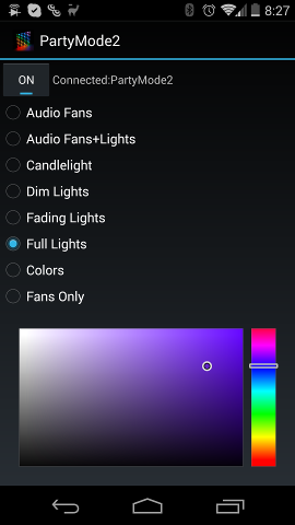
PartyMode 2.0 is an integrated lighting and audiovisual system for the dual purposes of creating useful lighting modes and creating an "instant party". It is the descendent of a larger PartyMode system constructed in 2007 in a student computer lab built for the same purposes (as well, of course, as an electrical engineering project). The final PartyMode 2.0 system comprises the control circuitry, seven LED-lighted PC case fans forming a VU meter, and four high-power RGB LEDs arranged into two channels of two LEDs each. Controlled by a smartphone app or Bluetooth serial console, the system can be put into the following modes:
- Off: System will not react to anything
- Audio fans: VUfan VU meter will react to audio input
- Audio fans + lights: Both fans and LEDs will respond to audio input
- Candlelight: LEDs simulate the intensity, color, and physics of gentle candlelight. Also called "romantic mode"
- Dim lights: All LEDs set to 25% intensity
- Full lights: All LEDs set to 100% intensity. Not recommended for extended use due to LED and TIP120 heat generation
- Fading lights: Lights start at full and slowly fade to off. Good for setting before climbing into bed.
- Colors: LEDs constantly fade slowly around the RGB spectrum.
- Fans Only: All fans are powered for illumination and ventilation; LEDs are off.
- Solid Color: The color selection area can be used to select a color and intensity for all LEDs.
The documentation herein presents the history and technical details of the PartyMode system, as well as additional media demonstrating the system's capabilities. First, it goes through the history of PartyMode starting from the first full-scale deployment in a computer lab called the μLab and continuing up through the present day. It then shows videos and pictures of the final PartyMode 2.0 system, later expanding on how the system is built, including the schematics, board layouts, and necessary software. IF you have any questions, feel free to contact me, or post your question on the Cemetech forum.
2. Photos and Videos3. History
PartyMode 1 was first created between May and December 2007 in the μLab of the Electrical Engineering Department at the Cooper Union. The original PartyMode was a combination of systems intended to provide an "instant party" as well as amazing sound in a college electrical engineering laboratory. The component systems, called MSS 24.4, VUFan, and DiscoScreens, together created a powerful audiovisual experience, and if the system could have been brought to fruition, it would have also included disco balls and more elaborate lighting effects. Unfortunately, political tensions and new regulations at my undergraduate institution brought a premature end to the project, and due to fear of retribution, I have not published details of the original PartyMode installation until now. Unfortunately, this also means that the project is very poorly documented: very few photographs and no videos of the original PartyMode exist. Four years later, I tested out the remnants of the system in my bedroom, and after a lull of three additional years, I devoted my focus to finishing the system. These three major revisions are as follows:
- Summer-Fall 2007, PartyMode 1: "Party at the touch of a button:" 22.4-channel sound, VUfan, DiscoScreens, and planned (but incomplete) illumination.
- May 2011, PartyMode 2 with LCDs: PartyMode 1 software and VUfan reconstituted in my bedroom, controlling four LCDs.
- Spring-Summer 2014, PartyMode 2.0: Final form of the project, a miniature form of the original planned PartyMode 1. RGB LED illumination synced to music, VUfan VU meter, 5.1 surround sound, Bluetooth control.
PartyMode in any form was first documented online in a Cemetech topic, and described as "a network of systems designed to deploy an instant party in one of my school's computer/study labs at the press of a button".
Four of the systems had reached some semblance of their final form by the time the system was decommissioned, and a fifth was in the process of being planned and tested:
- VUfan: The VUfan sound visualization system was first documented with five sound-reactive LED-lighted computer fans, controlled by the audio processing software Discolitez running on a computer. The VUfan project was published on Hackaday (one of my first projects to be featured on that site); I later expanded it to seven fans, still controlled by a computer. PartyMode 2.0 is the first version of the system to use only a microcontroller for audio processing.
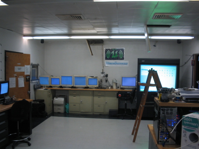
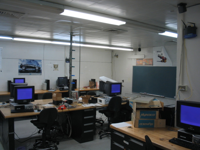
- DiscoScreens: The undergraduate lab in question had ten Dell workstations with CRT monitors. In addition, an eleventh computer had one LCD and five more CRT monitors connected through a VGA splitter. A program written in C++ could be launched over the network on each computer, creating a full-screen OpenGL buffer that would flash synchronized colors in time to music. The computer controlling the VUfan system also generated color and intensity information for DiscoScreens, producing brighter colors for louder music and switching the color on each detected beat in the music. Unfortunately, as video of DiscoScreens appears to be lost, the only documentation of the system are the few photos above and below as well as the source code for the DiscoScreens client.
- MSS 24.4: Short for "microLab Surround Sound", the sound system encompassed a rapidly-growing collection of speakers, subwoofers, and amplifiers, some purchased, some salvaged from dusty stockrooms, the remainder donated by friends and lab members. The 24.4 indicates that at the height of its power, the audio system included 24 speakers plus an additional 4 subwoofers, running the gamut from simple PC speakers to powerful custom-built amplifiers connected to 2-foot-tall cabinet speakers. Each of the speakers was safely mounted onto the ceiling of the lab, and the low-voltage wiring connected each speaker was safely run to a central audio splitter at the front of the room, again connected to the PC controlling VUfan and DiscoScreens.
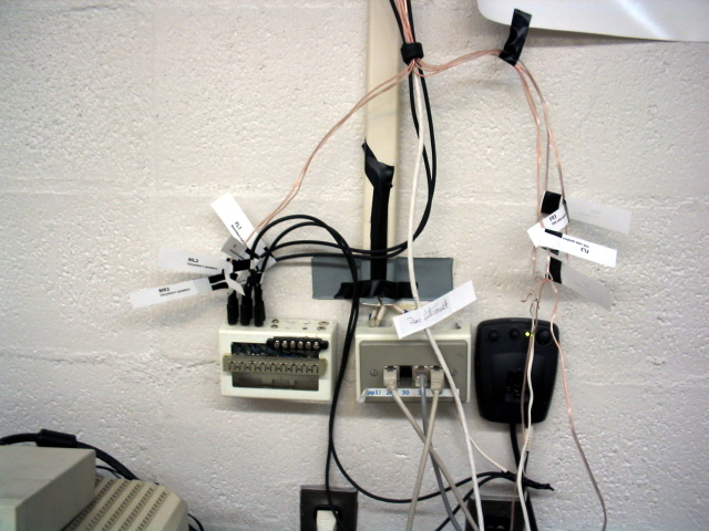
- Control panel: We wanted PartyMode to be the sort of system where you hit a button, and the room would transform from a study space to a celebration space. On the other hand, we wanted to avoid any liability or safety issues; we could not, for instance, modify the 120V electrical wiring in any way. Therefore, the system was controlled by a set of low-voltage circuits housed in an old 1U server, shown below, mounted under a table using copper strips. The room lights were turned on and off by an actuator attached to a rigid plastic sheet. While the actuator could pull all three light switches to the off position or push them to the on position, the lights could also be used normally by the room's occupants. That system is further detailed below. The three covered red switches and the "Easy" button were connected to the control computer, which handled actuating the light switch control and performing the necessary audio tasks.
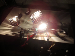
- Synchronized Lighting and Disco Balls: This fifth part of the system never surpassed the experimentation phase. If completed, it would have involved ceiling panels that retracted, one or more disco balls that would descend from the ceiling, and music-synchronized lighting to illuminate the ball(s). Bright incandescent bulbs took 9.0V and 2.7A total for three sets of three bulbs in heatsinks, or 300mA per bulb, were tested, but they generated extreme heat and quickly failed when powered at that level for extended periods. In addition, they were intended to be placed behind perforated ceiling panels, but the holes in the panels were so small that hardly any light was transmitted. Further experiments would have included brighter and cooler LED illumination.
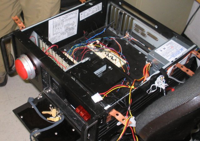
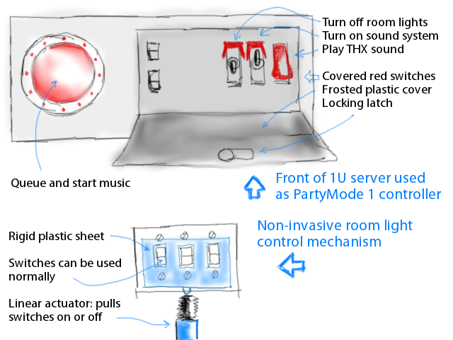
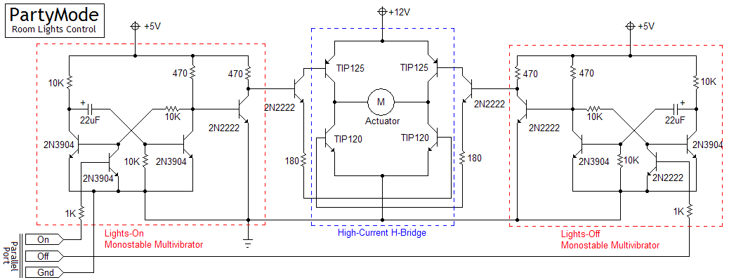
Unfortunately, a variety of circumstances prevented PartyMode 1.0 from every reaching fruition, and in fact, shortly after I graduated, the school demolished the building that housed the μLab, so the system as a whole is lost to the sands of time. Fortunately, I was able to salvage some components of the original system, namely the VUfan fans and controller as well as the DiscoScreens software.
3.2. Mini-PartyMode 2 with LCDsIn May 2011, I connected the salvaged VUfan and an RGB LED to an Arduino, fired up the Discolitez and DiscoScreens software packages, and tested out a miniature form of PartyMode on my four-monitor desktop at home. The results of that test are below; it functioned properly, and produced similar results to the old μLab system. However, it still required a computer to perform all of the audio processing, which I felt was a significant shortcoming. Taking the computer out of the loop would require more complex microcontroller software, and would remove the ability to flash screens in time with the music, but would also allow the system to work regardless of the sound input source or if the attached computer was on. In addition, I wanted to eventually experiment with other modes, such as using the fans for ventilation or adding RGB LEDs that could display patterns, act as mood lighting, or even be used as short-term primary illumination. The original news article for this miniature test of PartyMode can be found here.
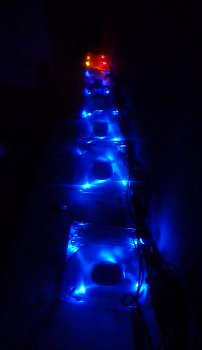
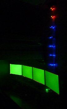
In April 2012, I ordered high-powered 3-Watt RGB LEDs from DealExtreme, and experimented with the component values necessary to properly power the LEDs. I designed a circuit using TIP120 Darlington transistors, similar to the VUfan controller, with carefully-computed resistor values to ensure the red, green, and blue elements in the LEDs would each receive the current power and current. By February 2014 I had begun to write an Arduino program that could control the lights in response to audio or in set patterns. Starting in April 2014, I renewed my efforts to finish the project, which included the following steps:
- Finalized the Arduino software with a new FFT library, recoding the other light modes, amd adding a serial control interface.
- Ordered a Bluetooth serial module and new RGB LEDs from DealExtreme.
- Constructied a perfboard version of the high-power fan and LED controller.
- Designed a PCB for the low-power control circuitry and had it fabricated using OSHPark.
- Wrote an Android app to control the system over Bluetooth.
- Combined all system components to complete PartyMode 2.0.
The final form of the PartyMode 2.0 system is a merger of the original multiple systems from PartyMode 1, namely DiscoScreens, VUfan, and the planned reactive illumination. It takes the form of 7 LED-lighted PC case fans and 4 high-power RGB LEDs connected to a pair of controller PCBs. The high-power controller is responsible for switching the LEDs and fans, while the low-power controller uses an ATmega328p microcontroller and Bluetooth serial module to process audio and commands to determine how to switch the fans and LEDs. It is completely indepedent from any computer, unlike the first two iterations of the system. The high-level parts list is as follows (the individual controllers' components are listed below):
- 4x 3W (1W per diode) common-anode RGB LEDs mounted on heat spreader stars.
- 7x 12V LED-lighted PC case fans.
- 1x external hard drive power supply, delivering 5V (~2.5A) and 12V (~1A). My supply is a bit underspeced to deliver 2.5A at 5V.
- 1x low-power controller PCB including components, programmed ATmega328p, and Bluetooth serial module.
- 1x high-power controller PCB including switching for 7 PC case fans and 6 channels of high-power LED (RGB x 2).
The RGB LEDs that I chose for the system are bright without requiring excessive power or generating extreme heat. Unfortunately, they are both common anode and are poorly documented. Based on the available documentation for the peak current and recommended voltage for each diode in the LEDs, I designed a set of three control blocks, each of which is capable of powering a pair of R, G, or B diodes in parallel. The blue and green diodes' requirements were close enough that I was able to use the same component values for both, while the red diodes required a different design. In addition, these computations assume that the switching element is a TIP120 Darlington transistor, and account for the characteristics and voltage drop of this component. A future design might make use of FET-based constant-current drivers.
The first step of computing the necessary parameters for the LED switching circuits was to model the circuit for a single diode. The heart of the circuit is a TIP120, a Darlington amplifying power transistor with gain Β=1000. Assuming a resistor RB on the base of the transistor creating a base current IB, the collector-emitter current ILED could thus be computed. Given the current ILED and a desired voltage drop VLED across the diode, the current resistor RLED can be chosen. The following circuit model and equations govern ILED and VLED given these constraints:
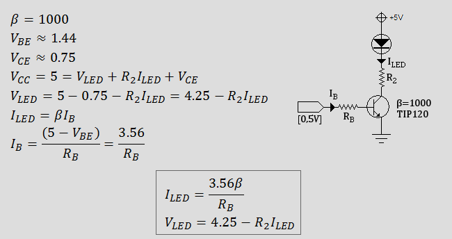
The next step was to experimentally determine the correct current and voltage through the diodes at maximum brightness. A simple circuit similar to the one above was constructed, starting with three 15-ohm resistors in parallel forming a 5-ohm, 0.75W R2, and a single 15K resistor as RB. The resistor values were varied, the brightness of the diode was measured, and the voltage and current were measured to find the lowest current at which the diodes remained at apparent maximum intensity. This process was repeated for the red, green, and blue diode in each LED, producing the following figures for VLED and ILED at maximum brightness:
- Red: 2.277V, 335mA
- Green: 2.838V, 252mA
- Blue: 2.94V, 236mA
The final step was to use these figures to determine the RB and R2 values to use in the final circuit. The blue and green requirements were close enough that the same values were used for each, while separate values were chosen for the red diode. In addition, because two RGB LEDs are used in parallel on each set of three TIP120 drivers, ILED was doubled for the final computations:
- Red RB: 3560/0.67 = 5.3Kohm (Used: 7.5Kohm after experimentation)
- Red R2: (4.25-2.277)/0.67 = 2.944 ohm @ 1.3W (Used: 4 ohm @ 1.5W)
- Green RB: 3560/.504 = 7.06Kohm (Used: 9.1Kohm after experimentation)
- Green R2: (4.25-2.838)/0.504 = 2.801 ohm @ 711mW (Used: 2.5 ohm @ 1.0W)
- Blue RB: 3560/.472 = 7.54Kohm (Used: 9.1Kohm after experimentation)
- Blue R2: (4.25-2.94)/0.472 = 2.775 ohm @ 618mW (Used: 2.5 ohm @ 1.0W)
The LEDs were installed in pairs, with two LEDs at each side of the room to respectively react to the left and right channel of any audio playing. Each pair is connected in parallel, and the two LEDs in each pair cannot be controlled independently. The LEDs have a very wide viewing angle, but are uncomfortable to look at directly, so a diffuser made from a Poland Spring water bottle cap was added on top of each LED, as shown below.
4.2. Low-Power Controller
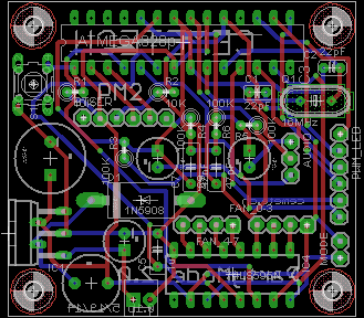
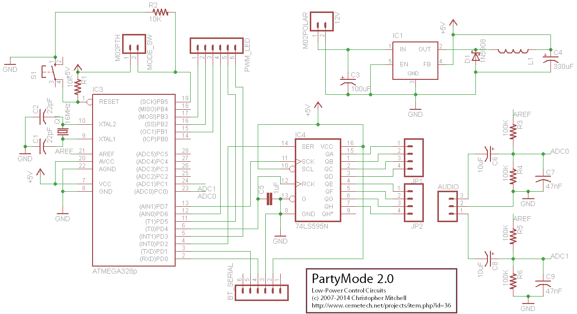
The low-power controller is responsible for determining the current state of the fans and LEDs. At its heart is an ATmega328p microcontroller, the same microcontroller used in the popular Arduino development board. A Bluetooth serial module communicates with the ATmega to relay commands from attached devices such as smartphones, and an SN74HC595 latching shift register is used to multiplex the ATmega's outputs to control the VUfan fans. Two analog circuits inhabit the low-power control board: a 5V switching regulator used to deliver clean 5V to the ATmega and attached components, and a pair of conditioning circuits to DC block, bias, and smooth the two audio channels delivered to the ATmega. The complete schematic for the controller is shown below.
Components
- 1x ATmega328p with 32KB of Flash, 1KB of EEPROM, and 2KB of RAM
- 1x 16MHz crystal
- 2x 22pF ceramic capacitors
- 2x 10Kohm resistors @ 0.25W
- 1x Normally-Open momentary pushbutton (for reset)
- 1x 100uF @ >12V electrolytic capacitor
- 1x 330uF @ >5V electrolytic capacitor
- 1x 330mH inductor
- 1x 1N5908 Schottkey diode
- 1x LM2575T-5.0 fixed-voltage 5V switching regulator
- 2x 10uF electrolytic capacitor
- 4x 100Kohm resistors @ 0.25W
- 2x 47nF ceramic capacitors
- 1x SN74HC595 latching shift register
- 1x HC-05 Bluetooth serial module on carrier board with 0.1" header
- Assorted female headers
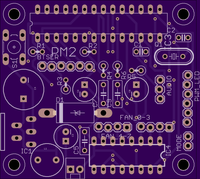
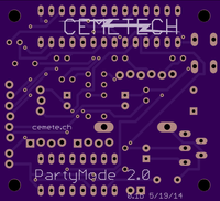
The images below show the progression of the low-power controller from a breadboarded prototype including the Bluetooth module, audio filtering circuitry, and 74LS595 connected to an Arduino, up to a complete fabricated and populated PCB. The board itself includes the switching-mode power supply necessary to power itself, as well as female headers to connect the output signals to the high-power control board. A 15-pin D-sub connector transfers the fan and LED signals as well as a ground from the low-power board to the high-power board.
Low-Power PCB Design Download
![]() PartyMode 2.0 Firmware, App, and PCB Design
PartyMode 2.0 Firmware, App, and PCB Design
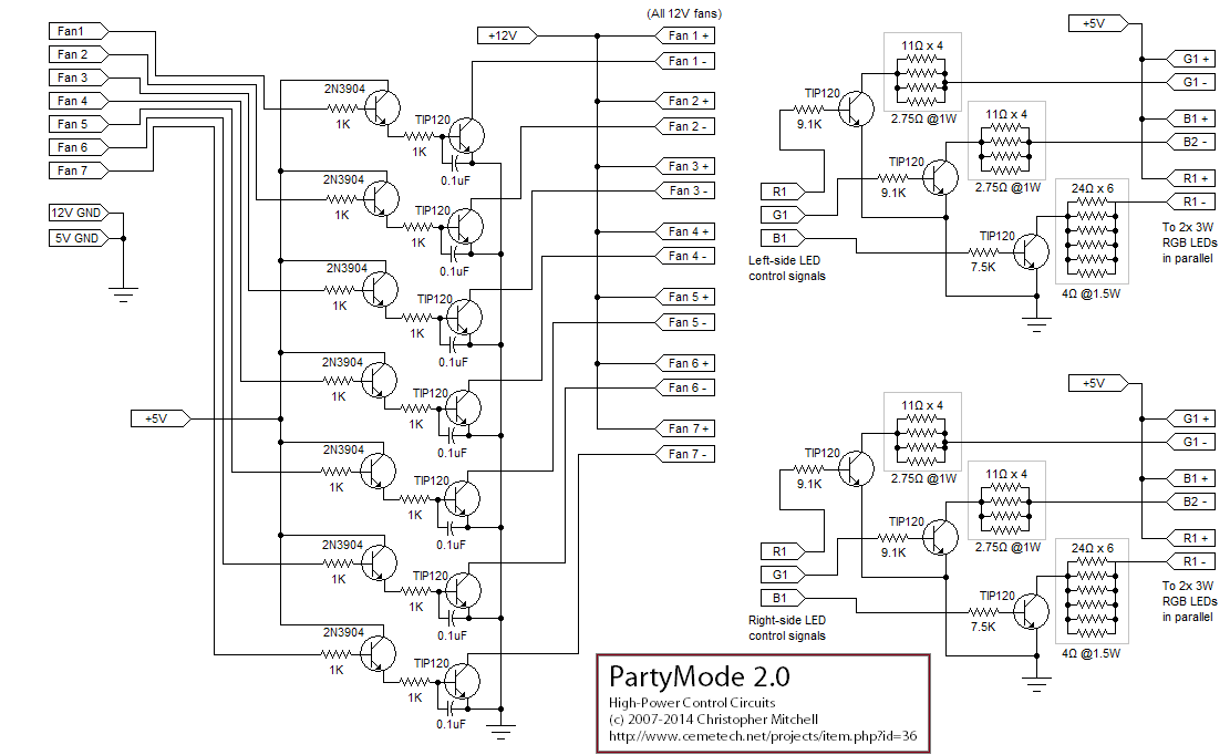
The high-power controller uses the TTL switching signals from the low-power controller board to switch the fans and RGB LEDs on and off (and in the case of the LEDs, perform PWM switching). It contains two types of circuits: transistor pairs that switch the 12V fans from a TTL signal, and carefully-computed switched supplies for the red, green, and blue diodes in each LED. The complete parts list and schematic can be seen below. The section for switching each fan is identical, and the sections for switching the left and right RGB channels are identical to each other. Note that the red diode control is not the same as the green and blue diode control, due to the lower current requirements of the red diode.
Components
- 13x TIP120 Darlington switching transistors
- 4x 2.75 ohm, 1W resistors (can be built from 16x 11 ohm resistors @ 0.25W)
- 2x 4 ohm, 1.5W resistors (can be built from 12x 24 ohm resistors @ 0.25W)
- 4x 9.1Kohm resistors @ 0.25W
- 2x 7.5Kohm resistors @ 0.25W
- 7x 2N3904 switching transistors
- 14x 1Kohm resistors @ 0.25W
- 7x 0.1uF electrolytic capacitors
- Assorted female headers
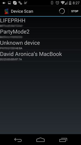
The completed PartyMode 2.0 system requires two pieces of software: the firmware to run the ATmega328p microcontroller, and an Android app that controls the system over Bluetooth. Any device with a serial terminal and a Bluetooth transceiver could be used to control the system, or the Bluetooth serial module could be replaced with a wired serial connection, but the Android app provides a much more user-friendly way to control the system. Screnshots from the app are shown below. Together, the ATmega firmware and the app permit the PartyMode 2.0 system to be set into the nine modes discussion at the beginning of this writeup.
The firmware for the ATmega328p was developed using the Arduino IDE, but foregoes the vast majority of the Arduino abstractions except the bootloader and the Serial library. Instead, it accesses the digital ports directly to perform output operations, sets up a custom ADC interrupt capable of sampling both the left and right audio channels and storing the values fetched to RAM buffers, and directly sets up the ATmega's PWM modes. By writing bare-AVR C rather than working through the Arduino API, in many cases latency was reduced by a factor of 10, at the cost of additional code complexity. The firmware uses the FastFFT library to analyze the sampled audio data, and the Piccolo project created by Adafruit was consulted as a reference for using the FastFFT library. Finally, because the firmware currently weighs in at roughly 7KB of binary code, ample space is available for future features and new illumination modes.
Firmware Download
![]() PartyMode 2.0 Firmware, App, and PCB Design
PartyMode 2.0 Firmware, App, and PCB Design
Advertisement


